


As bandwidth demand from AI servers and data centers continues to climb, 800G and 1.6T optical transceivers have become the mainstream specification for AI cluster interconnects, and module power density is rising just as fast. Inside a single optical module, high-power DSPs, laser diodes, and silicon photonic engines — all highly temperature-sensitive components — sit in close proximity to open optical coupling surfaces. This means that selecting a thermal interface material (TIM) for an optical module can no longer be about thermal conductivity alone; it must also account for whether the material's volatile byproducts could contaminate nearby optical surfaces. This article examines both the thermal design challenge and the siloxane contamination risk to explain the technical value of non-silicone TIMs in AI optical module applications.
Why Thermal Design for AI Data Center Optical Modules Is Becoming More Demanding
According to market research from Fortune Business Insights, the global optical transceiver market is projected to grow from USD 17.15 billion in 2026 to USD 46.12 billion by 2034, a compound annual growth rate of 17.00%. TrendForce data further shows that the market for Ethernet optical transceivers focused on AI cluster applications is expected to expand from USD 16.5 billion in 2025 to USD 26 billion in 2026 — growth of more than 50% in a single year — reflecting the rapid scale-up of demand for high-speed optics driven by AI infrastructure buildout.
As transmission specifications evolve from 400G to 800G and 1.6T, per-module power consumption is rising in step. Industry data indicates that 800G pluggable modules typically dissipate around 15 W, while power targets for 1.6T modules climb further to roughly 20–25 W for client-side optics and 25–30 W for data center interconnect optics. Thermal headroom in existing pluggable form factors is already tightening at these power levels, prompting the industry to move toward package designs with more complete thermal structures. Managing higher power within a constrained module volume makes the thermal interface between the DSP, laser engine, and heat-dissipating structure a critical factor in both overall cooling efficiency and signal stability.
Lasers and Silicon Photonic Engines Are Extremely Temperature-Sensitive
Laser diodes inside optical modules tolerate temperature variation far less than typical digital chips. For a common distributed feedback (DFB) laser diode, industry measurement data indicates its emission wavelength shifts by approximately 0.1 nm/°C as temperature rises. Without adequate temperature control, this drift can push the wavelength outside the channel specification, degrading — or even failing — the signal.
As co-packaged optics (CPO) technology develops, the micro-ring resonators commonly used in silicon photonic engines are even more temperature-sensitive. Industry technical sources indicate their resonant wavelength shifts by roughly 80 pm/°C. Without a stable thermal path, temperature fluctuation can push the resonant ring off its operating point entirely. This places higher demands on the stability and reliability of thermal interface materials in CPO architectures than in conventional pluggable modules.
Co-Packaged Optics Concentrates the Thermal Density Problem
CPO technology tightly integrates the optical engine with the switch ASIC. While this substantially reduces electrical losses and power consumption — Broadcom's published data shows its CPO solution consumes roughly 5.5 W per 800Gb/s port, versus approximately 15 W for an equivalent pluggable module — it also concentrates heat sources within a single package. Industry analysis indicates that a 51.2T-class CPO switch can dissipate more than 1,500 W from optical I/O alone, a thermal density that exceeds what air cooling can handle; most CPO switch platforms have therefore adopted liquid cooling as the standard thermal solution. Whether the architecture is air-cooled or liquid-cooled, the thermal interface material remains an indispensable link between the heat source and the cooling structure.
Siloxane Off-Gassing: An Easily Overlooked Contamination Risk at Optical Coupling Surfaces
Silicone-based TIMs have long been widely used in general electronics cooling applications thanks to their flexibility, surface wetting, and heat resistance. However, silicone polymers may contain incompletely reacted, low-molecular-weight cyclic siloxanes (chemical formula HO–[Si(CH₃)₂O]n–H), which are volatile and already show some tendency to off-gas at room temperature. Inside an optical module, continuous component heating combined with a relatively enclosed internal environment can further increase this off-gassing rate.
It's worth clarifying an important distinction here: ASTM E595 (which includes TML and CVCM metrics), commonly referenced for aerospace and vacuum applications, is designed to evaluate total mass loss and collected volatile condensable material under vacuum conditions. It applies to vacuum chambers — not to the atmospheric-pressure, enclosed housing environment of a ground-based data center optical module. The two should not be conflated. That said, even under atmospheric pressure, low-molecular-weight siloxanes can still volatilize as temperature rises and recondense on cooler internal surfaces — including fiber end-faces, lenses, and laser/photodetector windows, all open optical coupling surfaces. Research has identified siloxane as a common and difficult-to-remove source of molecular-level contamination in precision optical systems, capable of reducing transmittance and degrading imaging or signal transmission quality; this type of contamination is often nearly impossible to fully remove through standard cleaning.
For an optical module, once an optical coupling surface is contaminated at the molecular level, insertion loss and signal integrity are directly affected — and in most cases, field cleaning or replacement is not possible after the module has been assembled. This makes risk control at the material-selection stage especially important.

The Technical Answer: Non-Silicone Thermal Interface Materials
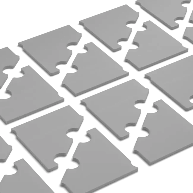
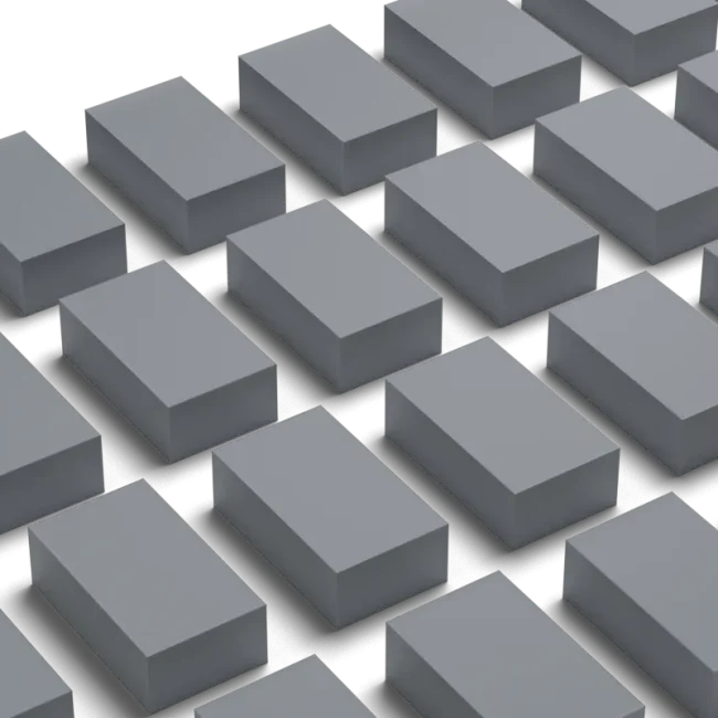
To reduce the risk of siloxane contamination while maintaining the high thermal performance modules require, non-silicone (silicone-free) TIMs have increasingly become an option for thermal design in optical modules, precision optical instruments, and other contamination-sensitive electronics. LiPOLY's non-silicone thermal pad series and non-silicone thermal grease series, for example, use a resin base that contains no siloxane backbone. Gas chromatography testing confirms that low-molecular-weight siloxanes (D3 through D20) are not detected (N.D.), and the product lines are explicitly rated for optical instruments, hard disk drives, 5G, and new energy vehicles — all contamination-sensitive applications.
On the thermal performance side, non-silicone materials do not sacrifice thermal conductivity by removing the siloxane backbone. Representative specifications for select LiPOLY non-silicone products are listed below for initial engineering evaluation:
| Product Model | Form | Thermal Conductivity (W/m·K) | Low-Molecular Siloxane (GC) | Primary Applications |
|---|---|---|---|---|
| N800A-s | Thermal Pad | 9.0 | Not Detected (N.D.) | Optical instruments, new energy vehicles |
| N800B | Thermal Pad | 13.0 | Not Detected (N.D.) | Optical instruments, 5G high-density modules |
| N800C | Thermal Pad | 17.0 | Not Detected (N.D.) | Optical instruments, precision electronics |
| N-putty5 | Thermal Gap-Fill Putty | 9.0 | Not Detected (N.D.) | Precision electronics, 5G communication equipment |
Full specifications are subject to LiPOLY's official product datasheets. Thermal conductivity is measured per ASTM D5470, LiPOLY's internal reference test method.
Selection Guidance: Matching Material Format to the Thermal Path
In practice, optical modules typically have two main types of thermal interfaces. The first is between the DSP or driver chip and the metal housing or heat sink, which generally demands higher thermal conductivity and compression performance — a non-silicone thermal pad is well suited here, balancing tolerance compensation with the need for cleanliness. The second involves interfaces requiring greater thickness flexibility and flow to fill irregular gaps, for which a non-silicone thermal putty or grease may be more appropriate. Regardless of format, siloxane off-gassing risk and thermal performance should both be built into the material evaluation criteria from the early design stage — not treated as a decision based on thermal conductivity alone.
Frequently Asked Questions
Q1: Does this mean silicone-based TIMs can never be used in AI optical modules?
Silicone-based TIMs still offer excellent flexibility and heat resistance, and remain suitable for locations away from open optical coupling surfaces where there is no enclosed-contamination concern. But where the thermal interface sits near a fiber end-face, lens, or laser/photodetector window, evaluating a non-silicone material first is recommended to reduce the risk of molecular siloxane contamination.
Q2: Does a non-silicone TIM sacrifice thermal performance compared to a silicone one?
Not necessarily. Commercially available non-silicone thermal pads already reach thermal conductivities of 17.0 W/m·K — comparable to, or higher than, silicone materials in the same class. Selection should be based on actual specification comparison rather than an assumption that non-silicone materials underperform.
Q3: Can ASTM E595 TML/CVCM data be used directly as a pass/fail criterion for TIMs in AI optical modules?
ASTM E595 is designed to evaluate volatile behavior under vacuum conditions and applies to satellites, space payloads, and similar vacuum applications. Data center optical modules operate in an enclosed, atmospheric-pressure environment, where the off-gassing mechanism differs from vacuum conditions. ASTM E595 data can serve as one reference point for a material's general low-volatility profile, but it should not be treated as an equivalent measure of atmospheric-pressure contamination risk. Gas chromatography results for low-molecular-weight siloxanes under atmospheric conditions (e.g., D3–D20 not detected) are the more directly relevant reference data.
LiPOLY's Non-Silicone Thermal Material Solutions
As AI data centers continue to advance toward 800G, 1.6T, and co-packaged optics — higher speed and higher power density at every step — TIM selection for optical modules must address both thermal performance and optical surface cleanliness at the same time. LiPOLY offers a range of non-silicone thermal pads and thermal greases, along with product datasheets, gas chromatography test data, and samples to support engineering evaluation and validation.
Contact LiPOLY to discuss thermal material selection for AI optical modules, optical transceivers, and high-speed computing platforms.
References
- Fortune Business Insights — Optical Transceiver Market Size, Share, Trends [2034]
- TrendForce — Global AI Optical Transceiver Market to Reach US$26 Billion in 2026
- FiberMall — Technology Route from 400G to 800G to 1.6T Optical Transceivers
- FiberMall — Optical Transceivers Overcome Heat
- Laser Focus World — Optical transceivers can beat the heat in the era of high-speed data centers
- APNIC Blog — Co-Packaged Optics: A Deep Dive
- MapYourTech — Co-Packaged Optics: Architecture, Status, and the Path to 1.6T Switches
- T.Global Corp — Silicone Thermal Interface Materials: Advantages and Considerations for Electronics
- E-Motec — Silicone in Thermal Interface Materials
- ResearchGate — Evaluation of outgassing contamination effects on optical surfaces of the LIL
- LiPOLY 2026 Product Catalogue (internal specification source)