


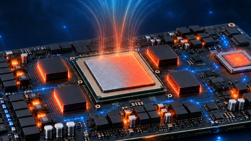
As AI GPU Module Power Density Rises, Every Heat Source Approaches Its Own Thermal Limit
An AI server GPU module is, in practice, a composite system built from several independent heat sources: the GPU compute die itself, HBM (High Bandwidth Memory) stacked within or beside the package, the VRM (voltage regulator module) that handles board-level power delivery, and AI Accelerators whose packaging closely resembles that of the GPU. Each of these components follows its own heat-dissipation path, packaging approach, and thermal design limit, yet all of them share the same underlying power-density growth curve of the module. Both the GPU die and the HBM stacks within the package rely on a chip-level thermal interface material (TIM-1 — the interface material between the die and the vapor chamber/cold plate) to carry heat away; the long-term reliability of this material directly determines whether the chip can stay within a safe junction-temperature range.
This article first surveys the thermal challenges facing the main heat sources inside an AI GPU module, as background for understanding the system-level picture. It then focuses specifically on the GPU's own chip-level TIM, covering the known limitations of conventional thermal grease and the technical specifications and reliability data of LiPOLY's PCM900 phase change material.
Main Heat Sources in an AI GPU Module and Their Respective Thermal Challenges
Before turning to TIM materials, it helps to clarify what each major heat source inside the module is dealing with — this explains why thermal design has become a core variable in overall AI server architecture.
- GPU compute die:AI server GPUs operate differently from traditional data-center workloads. During model training, GPUs often run at near-full load continuously for days at a time, keeping junction temperatures elevated for extended periods.
- HBM (High Bandwidth Memory):As GPU and HBM integration moves toward 3D stacking, vertical thermal resistance has become a new challenge. Research presented by imec, Belgium's microelectronics research center, at the 2025 IEEE International Electron Devices Meeting (IEDM) found that in a 3D HBM-on-GPU architecture without any thermal mitigation, peak GPU temperature under AI training workloads can reach 141.7°C — far beyond the operable range; combined technology- and system-level optimization is needed to bring peak temperature down to 70.8°C, on par with current 2.5D integration. This indicates that HBM's thermal bottleneck stems primarily from the vertical thermal resistance inherent to the packaging architecture — a packaging- and system-level issue.
- VRM (voltage regulator module):Board-level power delivery in an AI GPU module also has to manage heat generated under high current. Industry technical analysis notes that VRM circuit PCB design — heavy-copper power planes, low-inductance routing, and high-density decoupling capacitor arrays — is among the most demanding aspects of GPU baseboard design, requiring thermal and current-carrying capacity to be considered together.
- AI Accelerator:Whether GPU-based or built on another architecture, an AI Accelerator's chip packaging closely resembles that of a GPU — it likewise integrates a compute die, memory stacks, power-management ICs, and a chip-level thermal interface material, and faces thermal challenges highly similar to those of a GPU.
While these four component types together make up the full thermal picture of an AI GPU module, the interface-material selection considerations for each differ (for example, HBM's packaging structure and VRM's board-level heat path are both distinct from the application context of GPU chip-level TIM). The remainder of this article focuses specifically on the GPU's own chip-level TIM (TIM-1).
The Real Consequence of Chip-Level TIM Degradation: Throttling and Performance Loss
When a chip-level TIM's thermal resistance degrades over time, the consequence is not merely a rising temperature reading — it shows up directly in GPU compute performance. Industry analysis notes that once a high-end GPU's junction temperature reaches the critical 85–90°C threshold, the hardware initiates thermal throttling, automatically reducing clock frequency to prevent damage; a cluster running in a throttled state can lose up to 25% of its theoretical maximum performance — a meaningful increase in both runtime and cost for large language model training jobs that can span weeks. Academic research offers a concrete, quantified example: a paper on health management for large-scale training clusters found that as GPU temperature rises from 50°C to 77°C, core clock frequency can drop from 1.93 GHz to 1.38 GHz, noticeably delaying synchronization-sensitive training steps. These figures reflect a general industry pattern relating GPU junction temperature to performance, rather than test results for any specific TIM material — but they illustrate why chip-level TIM reliability is a variable that design teams must take seriously, rather than a simple spec-sheet comparison.
Known Limitations of Conventional Thermal Grease in Chip-Level TIM Applications
Conventional thermal grease has long been the mainstream choice for chip-level TIM, offering low initial thermal resistance and ease of application. However, comparative academic studies have found that thermal grease is prone to dry-out, pump-out, and increased void formation under prolonged thermal and power cycling — degradation that raises interface thermal resistance over time. Because phase change materials (PCMs) eliminate the dispensing and drying steps altogether, they are less prone to these voiding, pump-out, and interfacial-delamination issues.
How Phase Change Materials Address This Challenge: Working Principle and Physical Basis
A phase change material remains solid at room temperature, which makes it easy to handle in automated assembly and in transport and storage. Once temperature rises above its phase-change point, it softens into a semi-solid state that flows to conform to the microscopic surface irregularities between the heat source and the heat sink, lowering interface thermal resistance. Interface thermal resistance can be understood approximately through R ≈ BLT ÷ k, where BLT (Bond Line Thickness) is the thickness of the material once actually applied, and k is the material's thermal conductivity; for a given k, a thinner BLT means lower thermal resistance. This is why chip-level TIM specifications place particular emphasis on "the minimum achievable BLT," rather than simply comparing thermal conductivity figures — for chip-level applications where the gap between the die and the vapor chamber may be only tens of microns, whether a material can conform to a sufficiently thin BLT often has a more direct impact on final thermal resistance than a high thermal conductivity figure alone.
It is worth noting that academic literature has also found that phase change materials engineered for higher thermal conductivity through significantly increased filler loading can carry an elevated risk of leakage and mechanical failure. This is a general technical consideration for the phase change material category as a whole, not a result specific to any one product; it is included here purely as background, and product selection should still be based on the reliability test data of the individual product in question.
PCM900 Technical Specifications
LiPOLY PCM900 is a phase change material engineered for chip-level applications. It remains solid at room temperature for easy automated assembly, and softens and conforms once heated to a phase-change point of approximately 45°C. Published catalog specifications are as follows:
| Property | Value | TEST METHOD |
|---|---|---|
| Thermal conductivity | 9.0 W/m·K | ASTM D5470 |
| Phase Change Temperature | 45°C | – |
| Minimum Bond Line Thickness (BLT) | 24 µm | – |
| Application temperature | -60~150°C | – |
| Density | 2.70 g/cm³ | ASTM D792 |
| Surface / Volume Resistivity | >10¹² Ohm/Ohm·m | ASTM D257 |
Frequently Asked Questions
Q1: What are PCM900’s advantages compared with conventional thermal grease?
PCM900 remains solid at room temperature and can go straight into automated pick-and-place assembly, eliminating the dispensing, degassing, and drying steps required for conventional thermal grease. Comparative academic studies note that because phase change materials skip the dispensing and drying process entirely, they are less prone to the dry-out and pump-out degradation commonly seen with conventional thermal grease over the long term.
Q2: What is the practical significance of the 45°C phase-change temperature?
PCM900 stays solid below 45°C, making it easy to cut, transport, and place with automated equipment. Once the chip powers on and the interface temperature rises above 45°C, the material softens and flows to conform to the microscopic surface irregularities between the heat source and the vapor chamber, reaching the catalog's minimum 24 µm bond line thickness (BLT) — balancing ease of assembly with low contact thermal resistance.
Q3: Has PCM900's reliability been validated through long-term testing?
Yes. The catalog reports four reliability tests — thermal aging (125°C), high-temperature/high-humidity (85°C/85% RH HAST), thermal cycling (-40 to 125°C), and low-temperature exposure (-60°C) — run for as long as 1,000 hours or 500 cycles. Across all four, the change in thermal resistance stays within roughly 10% of the original value, indicating stable interface performance under sustained thermal stress.
Q4: What applications is PCM900 suited for?
Per the catalog's "Typical Application" listing, PCM900 is suited to AI/HPC (AI servers, GPUs), data centers (servers, networking equipment), consumer electronics (PCs, SSDs, game consoles), power (power modules, power supplies), and automotive electronics (ECU, BMS, OBC), and is available in 0.15 mm, 0.20 mm, and 0.25 mm thicknesses to suit different applications.
LiPOLY PCM900 Product Overview
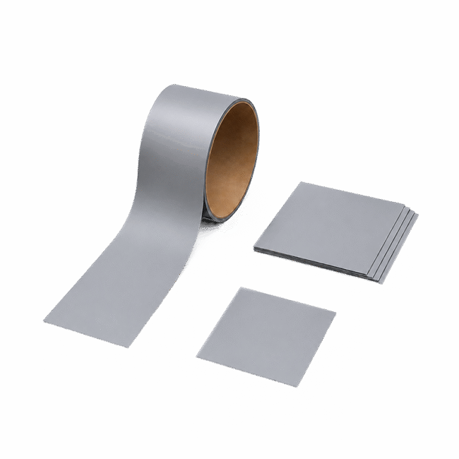
A high-performance phase change thermal interface material engineered for chip-level applications, with a thermal conductivity of 9.0 W/m·K and a 45°C phase-change temperature, suited to AI server, GPU, and other AI/HPC applications. Available in 0.15 mm, 0.20 mm, and 0.25 mm thicknesses, and can be supplied as roll, sheet, or die-cut format as required.
References
- NextPCB. “What Is an AI Server? Architecture, Components & PCB Requirements.”
- NextPCB. “GPU Rack Architecture: How AI Clusters Are Built from PCB to Rack.”
- imec. “Imec Mitigates Thermal Bottleneck in 3D HBM-on-GPU Architectures.” Presented at IEEE International Electron Devices Meeting (IEDM), 2025.
- TechRound. “The Hidden Bottleneck of the AI Boom: Why Thermal Throttling Is Slowing Down Your GPUs.”
- arXiv. “Guard: Scalable Straggler Detection and Node Health Management for Large-Scale Training.”
- IEEE Xplore. “A Comparison Study of TIM Degradation of Phase Change Material and Thermal Grease.”
- ScienceDirect. “Synergistically Reinforced Phase Change Thermal Interface Materials for High-Power Electronics: Low Resistance and Long-Term Reliability.”
- LiPOLY Ultra3065 Product Datasheet (Chinese / English / Japanese) — Internal Specifications
Related Products
Non-Silicone
NEW
Phase Change Materials