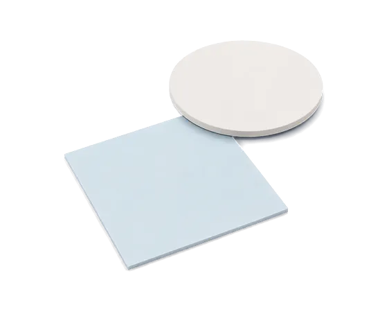
Thermal gap pad selection must account for gap size, thickness, hardness, compression ratio, thermal resistance, electrical insulation, handling and operating conditions. The right material can conform to the heat source and heat sink, reducing interface thermal resistance without placing excessive stress on the component.
Check the Gap and Fill Area
Measure the minimum and maximum gaps between the heat-generating component and heat sink. Include component height differences, PCB warpage and assembly tolerances in the assessment.
KEY POINT
Minimum and maximum gap
Component height differences
Positive and negative mechanical tolerances
Expected compression after assembly
TIPS
Choosing thickness from the nominal gap alone may overlook production tolerances. Some areas may lose contact, while excessive compression may increase stress on components.
Choose the Right Thickness
The pad must be thick enough to fill the gap and maintain full contact after compression, without adding unnecessary distance to the heat-transfer path.
KEY POINT
Uncompressed thickness
Actual gap size
Compressed thickness
Mechanical tolerance range
TIPS
A thicker pad is not necessarily safer. Excess thickness may increase thermal resistance, assembly pressure and lateral deformation.
Assess Hardness and Compression
Pad hardness affects conformity, compression, handling and the mechanical stress placed on the PCB and components.
KEY POINT
Maximum pressure the PCB and components can withstand
Required compression ratio
Contact-surface unevenness
Fastening pressure and uniformity
TIPS
Softer pads can accommodate tolerances and reduce assembly stress. If too soft, however, they may be harder to pick up, position or place automatically. Choose according to the process conditions.
Compare Conductivity and Resistance
Thermal conductivity describes the material’s ability to conduct heat. Actual cooling performance also depends on thickness, compression, contact area and how well the surfaces conform.
KEY POINT
Thermal conductivity
Actual application thickness
Contact after compression
Thermal resistance under different pressures
TIPS
Higher thermal conductivity does not always produce better cooling in the device. A pad that is too hard, too thick or poorly conformed may perform worse than a lower-conductivity material with better contact.
Check Electrical Insulation
When a thermal gap pad sits between an electronic component and a metal heat sink, confirm its electrical isolation capability against the equipment’s operating voltage and safety requirements.
KEY POINT
Dielectric breakdown voltage
Volume resistivity
Surface resistivity
Material thickness
TIPS
Do not judge insulation by appearance or feel alone. Check the electrical properties of wave-absorbing, graphite and other specialized composite materials separately.
Assess Form and Handling
Tack, reinforcement, toughness and release-liner design affect cutting, pick-and-place, installation and later rework.
KEY POINT
Sheet stock or custom die-cut shapes
Single-sided, double-sided, or non-adhesive
Fiberglass reinforcement
High-toughness construction
Release liner and pull-tab design
Manual or automated placement
TIPS
More tack is not always better. It helps positioning, but may complicate rework and cause tearing or residue during removal.
Assess Environment and Reliability
Under the actual temperature, humidity, pressure, vibration and service-life conditions, the pad must maintain its thermal performance, dimensions and compression behavior.
KEY POINT
Prolonged high temperature
Thermal cycling
High temperature and humidity
Continuous compression
Vibration and shock
Compression set
Change in thermal resistance after aging
TIPS
The maximum operating temperature is only a starting point. Confirm performance after prolonged aging, thermal cycling and continuous compression.
Check Special Requirements
Beyond heat transfer and gap filling, some equipment requires non-silicone materials, low outgassing, electromagnetic-wave absorption, low weight or coolant compatibility.
KEY POINT
Proximity to optical components or precision contacts
Use in vacuum or sealed environments
Need to absorb electromagnetic interference
Weight limits
Contact with immersion-cooling fluid
Need to reduce oil bleed and contamination
TIPS
Do not infer special properties from a product name alone. Non-silicone does not necessarily meet a low-outgassing requirement, and low-bleed does not mean zero oil bleed. Confirm with test data.
Special Requirements
Application
Suggested property
Optical lenses, precision contacts
non-silicone, low outgassing
Radar, 5G and millimeter-wave equipment
EMI Absorbers
Satellites, drones and mobile devices
lightweight, low density
High-voltage and power modules
electrical insulation
Sealed equipment and clean appearance
Low Oil Bleed
Single-phase immersion-cooling equipment
coolant compatibility
Validate Samples in the Device
Datasheets support initial screening. Final selection still requires testing in the actual equipment at the intended thickness, clamping pressure and operating conditions.
KEY POINT
Actual component temperature rise
Hotspot location
Degree of PCB bending
Pad compression and displacement
Thermal resistance after cycling
Material condition after disassembly
Oil bleed, swelling or contamination
Stability during prolonged operation
TIPS
Make sample testing as close to production conditions as possible, including pad dimensions, die-cutting method, clamping pressure and environment. This helps avoid a mismatch between laboratory and production results.
Quick Selection Guide
Need
Series
High power, lower thermal resistance
High Thermal ConductiveGap Filler Pad
General gap filling, broad specification choice
General-Purpose Gap Pads
Very small gaps and slim designs
Ultra-Thin Gap Pads
Lower stress on PCBs and components
Ultra-Soft Gap Pads
Complex die-cutting and automated handling
High-Toughness Gap Pads
Less oil bleed and visible contamination
Low-Bleed Gap Pads
Large sizes, die-cutting and dimensional stability
Glass-Fiber-Reinforced Gap Pads
Prolonged operation in coolant
Single-Phase Immersion-Cooling-Compatible Gap Pads
Designed for high-power chips, power modules and equipment with high heat flux. A highly conductive formulation and good compressibility fill contact gaps, reduce interface thermal resistance and transfer heat from components to the heat sink.
Available in a range of thermal-conductivity grades, hardnesses and thicknesses. Flexibility, compressibility, inherent tack and electrical insulation help accommodate mechanical tolerances in many consumer and industrial electronic devices.
FEATURE
layers
Broad Specification Range
multiple thicknesses, hardnesses and conductivity grades.
tile_medium
Tolerance compensation
accommodates component height and mechanical variation.
Designed for very small gaps and slim assemblies. The thin structure shortens the heat-transfer path while providing low thermal resistance, compressive strength and electrical isolation for high-power components in limited space.
FEATURE
drag_handle
Ultra-thin design
suits very small gaps and slim devices.
trail_length_medium
Shorter thermal path
reduces the distance from component to heat sink.
thermometer_minus
Lower thermal resistance
improves heat transfer across thin interfaces.
expand
Compressive stability
maintains strength in a thin structure.
flash_off
Electrical isolation
separates components from metal cooling structures.
Low hardness and high resilience help the pad conform to components and heat sinks under lower assembly pressure. It accommodates height variation and reduces the risk of PCB bending, chip stress and damage to fragile components.
High toughness and stretchability improve durability during cutting, handling and assembly. Narrow strips, openings and irregular shapes are less likely to tear or deform, making these pads suitable for automated processes and applications requiring rework.
FEATURE
receipt
Tear resistance
reduces damage during handling and assembly.
motion_mode
Shape stability
suits complex outlines and narrow die cuts.
my_location
Easier handling
supports automated pickup and accurate placement.
compress
Rework durability
resists tearing and deformation during repeated removal.
cards
Cushioning
absorbs vibration, shock and mechanical tolerances.
Designed to reduce oil bleed under prolonged compression and high temperatures. Less silicone oil migration helps limit dust pickup, electronic-component contamination and visible staining while retaining heat transfer, flexibility and electrical insulation.
FEATURE
format_color_reset
Less oil bleed
reduces migration under prolonged compression.
blur_on
Less contamination
lowers the risk of oil-film contamination.
flare
Cleaner surfaces
reduces dust adhesion and visible soiling.
lock_clock
Long-term stability
maintains thermal performance under continuous compression.
flash_off
Electrical isolation
combines heat transfer, compressibility and insulation.
A glass-fiber reinforcement layer improves dimensional stability and handling strength. It reduces stretching during pickup, die-cutting and assembly, making the material suitable for large sheets, complex shapes and automated processes.
FEATURE
dataset
Glass-fiber reinforcement
improves structural strength and durability.
compress
Rework durability
resists tearing and deformation during repeated removal.
surgical
Die-cutting flexibility
suits large parts, openings and complex shapes.
location_searching
Stable placement
improves automated handling and positioning accuracy.
Designed for single-phase immersion cooling, these pads maintain their structure and thermal performance during prolonged exposure to coolant. They serve as thermal interfaces for high-power components such as GPUs, AI accelerators and ASICs.
Note: Avoid stretching, folding or contaminating the pad during installation. Tighten evenly to the product’s recommended compression ratio. Too little compression can impair contact; too much can stress components and deform the material.
Feature Overview
Non-Silicone
Reduce Siloxane Outgassing and Contact Contamination
Evaluate material outgassing, condensable substances and water-vapor regain to reduce the risk of contaminating lenses, sensors and precision components in vacuum or sealed environments.
Low Outgassing
For Vacuum and High-Cleanliness Applications
The stable formulation is designed to limit oil migration and volatile emissions, helping reduce contamination of nearby components and improve long-term equipment reliability.
Reliability
Stable Under Heat and Thermal Cycling
Suited to prolonged high-temperature operation and thermal cycling. It helps reduce material softening, degradation, displacement and increases in thermal resistance, maintaining contact and heat-transfer reliability.
Immersion-Cooling Compatible
Retain Structure and Heat Transfer in Coolant
Designed for immersion compatibility, the material maintains its dimensions, structure and thermal performance during prolonged exposure to single-phase immersion-cooling fluid. It is suited to AI servers and high-performance computing platforms.
Electrical Insulation
Heat Transfer with Electrical Isolation
High volume resistivity and dielectric breakdown voltage provide electrical isolation between components and metal heat sinks, suiting power devices and high-voltage electronic modules.
Wave Absorption
Manage Heat and Electromagnetic Interference
Sheet-form material combines heat conduction with electromagnetic-wave absorption to help reduce signal interference across frequency bands and address hotspots. It suits millimeter-wave, terahertz, radar and communications equipment.
Lightweight
Lower Weight, Maintain Heat Transfer
Low-density materials reduce the weight of thermal-management structures while balancing cooling performance and weight limits. They suit satellites, drones and portable electronic equipment.
Thermal Pad Selection FAQs
How do thermal gap pads differ from liquid gap fillers?
A
Thermal gap pads are preformed sheets whose thickness and shape are easy to control. They can be applied or replaced directly and suit clean, fast assembly. Liquid gap fillers conform to complex surfaces and larger tolerances and are better suited to automated dispensing, but dispensing volume, curing and other process conditions must be controlled.
Does higher thermal conductivity always mean better cooling?
A
Not necessarily. Actual performance also depends on pad thickness, compression, contact area, surface flatness and interface thermal resistance. A highly conductive pad that is too thick, too hard or poorly conformed may perform worse than a lower-rated material with better contact.
How should I choose pad thickness?
A
Measure the minimum and maximum gaps and account for mechanical tolerances. Choose a thickness that maintains full contact after compression. A pad that is too thin leaves gaps; one that is too thick may increase thermal resistance and assembly pressure.
Is a softer pad always better?
A
No. Ultra-soft materials can reduce assembly stress and accommodate tolerances, but may be harder to handle, more prone to displacement or less suitable for automated assembly. Select hardness according to component pressure limits, pad area and assembly method.
When should I choose a glass-fiber-reinforced pad?
A
For large pads, complex shapes, narrow cuts, automated handling or repeated rework, the reinforcement layer improves dimensional stability and reduces stretching, tearing and deformation during assembly.
Thermal Solutions Expert
SHIU LI TECHNOLOGY CO., LTD.
Taoyuan City, Bade District, Yongfeng Road, No. 435
Product News | N700C, N800A-s, N800B, and N800C Non-Silicone Thermal Pads Comply with ASTM E595 Test Requirements. For detailed specifications, please refer to the product datasheets.